On Inputs and LEDs

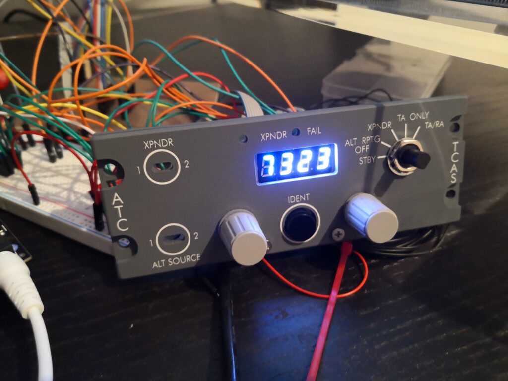
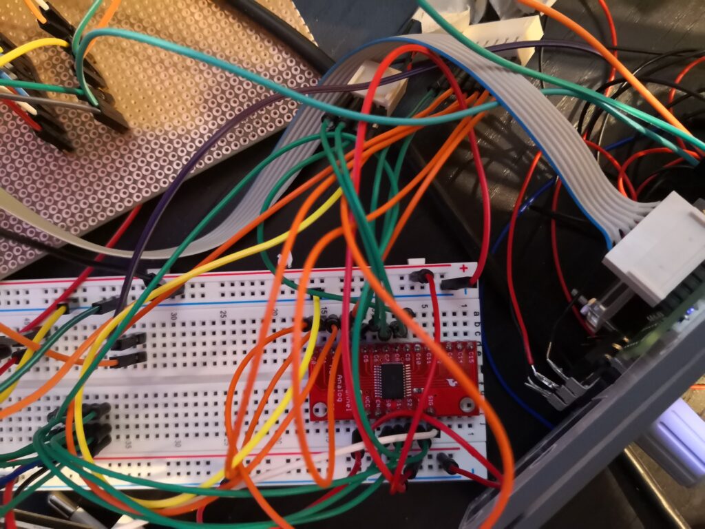
One of the the challenges I face is to find the proper way of wireing all the components, so that the cockpits remains “maintainable”. When I started building the pedestal my central component, so to speak – was a bread board. The Arduino, the Multiplexer boards, the 7 Segment PCB, everything is connected to it. While this works, it’s not a robust and long term solution.

Especially now, that I want to start adding more inputs and also LEDs into the Pedestal (the Cargo Fire Panel will be the next instrument) i have to find a solution for that messy setup.

Speaking of LEDs. SimVim recommends a couple of LED drivers to use, which is nice. My personal problem is, that I like to order IC and other components via Digikey and they don’t offer any of the ICs listed to be used a LED drivers.

So I was looking for an alternative to the often mentioned DM13 LED driver and found the STP16CPC26MTR. The specifications are almost identical and they work like a charm with SimVim aswell.

For inputs I used the SimVim recommended CD74HC4067 multiplexer cards. Currently I am working on another PCB which will use the IC directly (CD74HC4067M96) to combine In- and Output functionality and hopefully the days of the breadboard and “messy” setup are over.
Getting started with inputs

So after testing the Max7219 drivers and getting all desired digits to work, I gave Inputs a try. So the goal was to “migrate” my already working OpenCockpits instruments to SimVim.

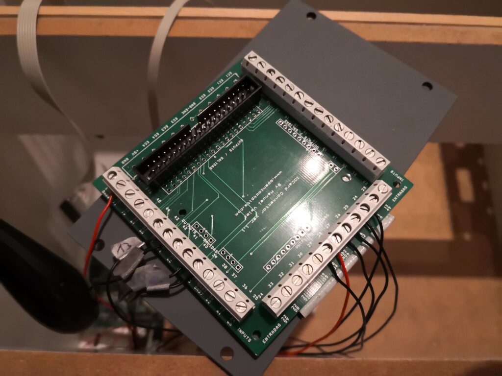
In order to reach that goal, the easiest would have been to make OC’s Inputs card somehow compatible with SimVim, meaning I’d just need to find a way, of connecting the multiplexer cards. Well – it turned out, that the pin positions don’t correspond with the actual “Input” pin. In fact, they seem to be completely random (I guess they are not, but I didn’t really bother yet to dig deeper).

So instead I disconnected the wires of my transponder from the Screw Terminal crimped them and put a connector on them to try it out.

For the transponder we are talking about the following components, which needed to be connected and configured:

  • 1 Momentary Push botton (used for IDENT)
  • 2 rotary Encoders (used for outer and inner Squawk)
  • 1 Rotary switch (Used for modes)

After hooking them all up to the breadboard I gave SimVim’s configurator a go, created the config, fired up X-Plane AAAAANDDD it worked. At least thats what I though initially. The rotary switch – well – switched through the modes. But when hitting ‘TA/RA’ (which was configured to be on ‘C5’ of the multiplexer Board, SimVim got input from IDT, which was configured on channel 9. I checked and double checked the wires an connectors, but only the ones from the instrument to the multiplexer board. It turned out,did a mistake hooking up the address lines to the multiplexer board, resulting in mixed up addresses. So, instead of address 0101, Arduino got 1001. In the end I decided to redo the wireing completely and the problem was solved (to be honest, I really need to improve my cable management).

It still looks like a mess, but hey, at least it worked!

After I had my SimVim config done and everything looked good that far, I also connected the 4 digits I previously used with the transponder to the prototyping PCB. Last time I soldered one Max7219 driver to a blank PCB, added some male pin header and starter connecting Segments and digits. As you could see in my previous post, I already had the segments working that far. I added them to the config and hey – I got my transponder working again!

Since this is just a prove of concept, I’m looking forward to redoing all cables, connectors, etc. in a nice, clean way.