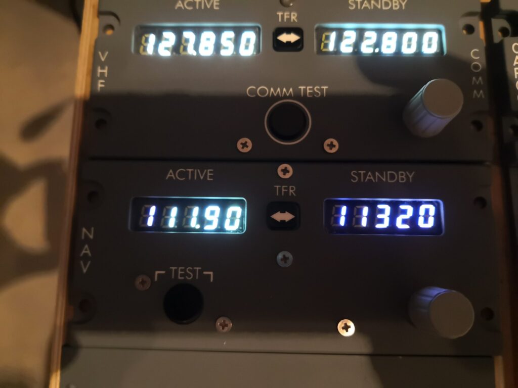
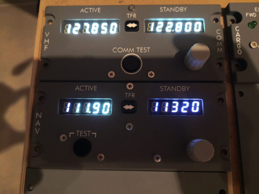
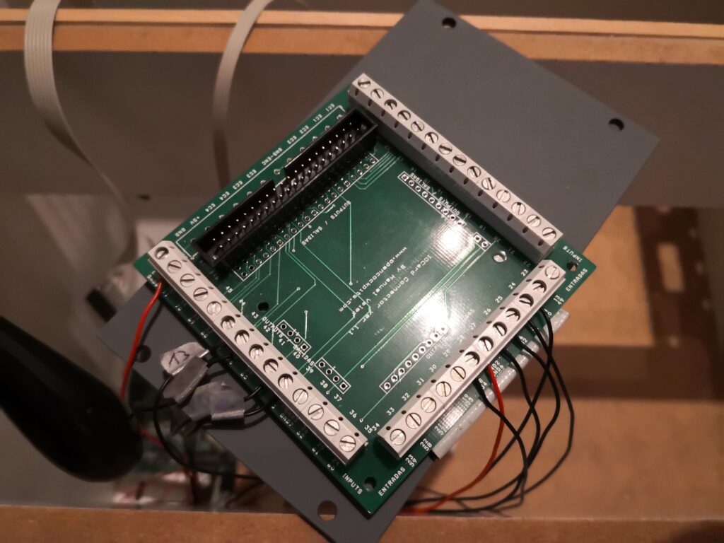
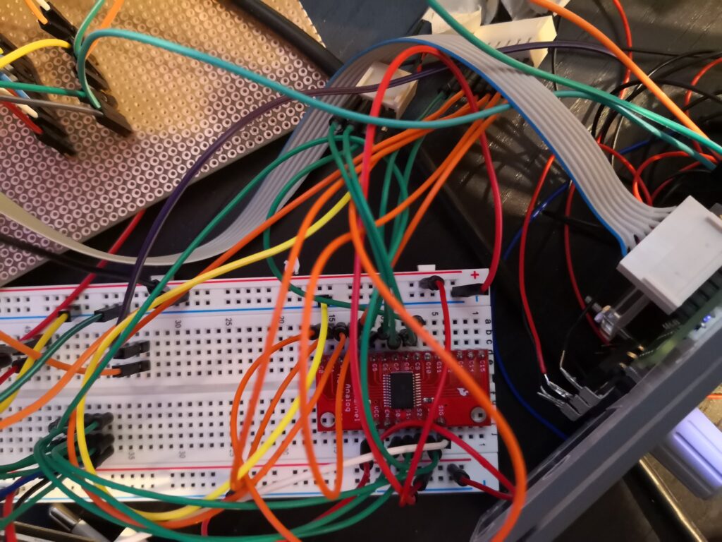
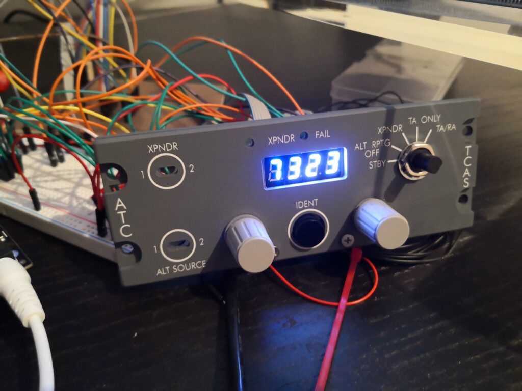
After getting the 7 segment LEDs working on my XPDR, I continued with my already existing COMM and NAV instruments. I used a breadboard aswell and they worked like a charm. The only problem was the sheer amount of cables to connect the segments to the drivers and frankly a breadboard + some cables didn’t really sound like a good permanent solution.
To fix that problem, I decided to design my own PCB for that case. I used kicad last year and started designing a PCB which I planed to use for a Boeing Style FMC, but I didn’t finish until now. Thanks to Chriz2600 , a colleague of mine (and by the way a real pro in the field). I got quite a lot of help from him in getting started with Kicad and PCB design. If you are into Retro gaming, you must check out his projects!
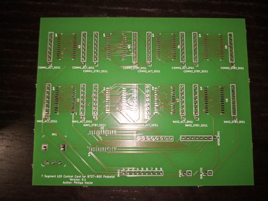
The idea for my PCB was to organize the 7 segments by Instrument and driver, meaning I’d use 1 driver per display (e.g. the COMM panel would need 2 ICs, one for ACT and one for STBY frequency). Since the drivers – as stated before – are actually pretty pricy, the conecpt is maybe not optimal, especially because you can drive up to 8 segments per IC, but I’d only need between 4 (for the transponder) and 6 (for COMM). In terms of structure on the board, I decided to place male pins left and right IC, the left side for the segments, the right side for the digit. The chips are aligned according to their position on the pedestal. In the end, I came up with the following design:

The first working design of the display card
As you can see, the first row is reserved for COMM Panels. One on the Captain’s side, one on the FO’s side. Of course they can be used for other instruments, if needed.
The second row is for the NAVS (Captain’s and FO’s aswell) and the last IC is for the XPDR.
RV1 is reserved for a potentiometer, which allows to adjust the brightness of all the instruments used. MUX1 is used to connect the PCB to a multiplexer card. Numbers 1 through 9 correspond to the IC (from left to right. Meaning COMM1_ACT is MUX1 1 and XPDR is MUX1 9). DIN_CS1 are connected to the corresponding Outputs of the Arduino (aka D and L).
For manufacturing I decided to go with Aisler. From placing the order to receiving the PCBs it took around a week. The price is ok aswell: 3 PCBs cost 33 € (incl. shipping).
Soldering was easy for the most parts, since all connectors are just simple through hole. The SMD ICs were a bit tricky in the beginning though. What helped was to fix them in position with a bit of tape. You can leave it on until you’re completely done, since it can also act as an indicator if the chip maybe got a bit too hot and you should wait a bit before continueing to let it cool down.
Initially I just finished the transponder part to check if there were any general problems with the layout. This is what the first try looked like.
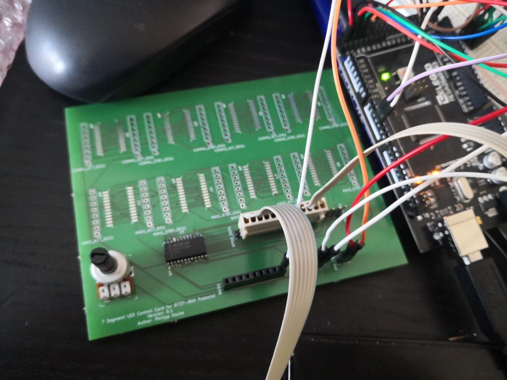
To be honest I was kinda surprised that it actually worked. 😀
Since I tested the functionality successfully, I continued with COMM1 and NAV1.
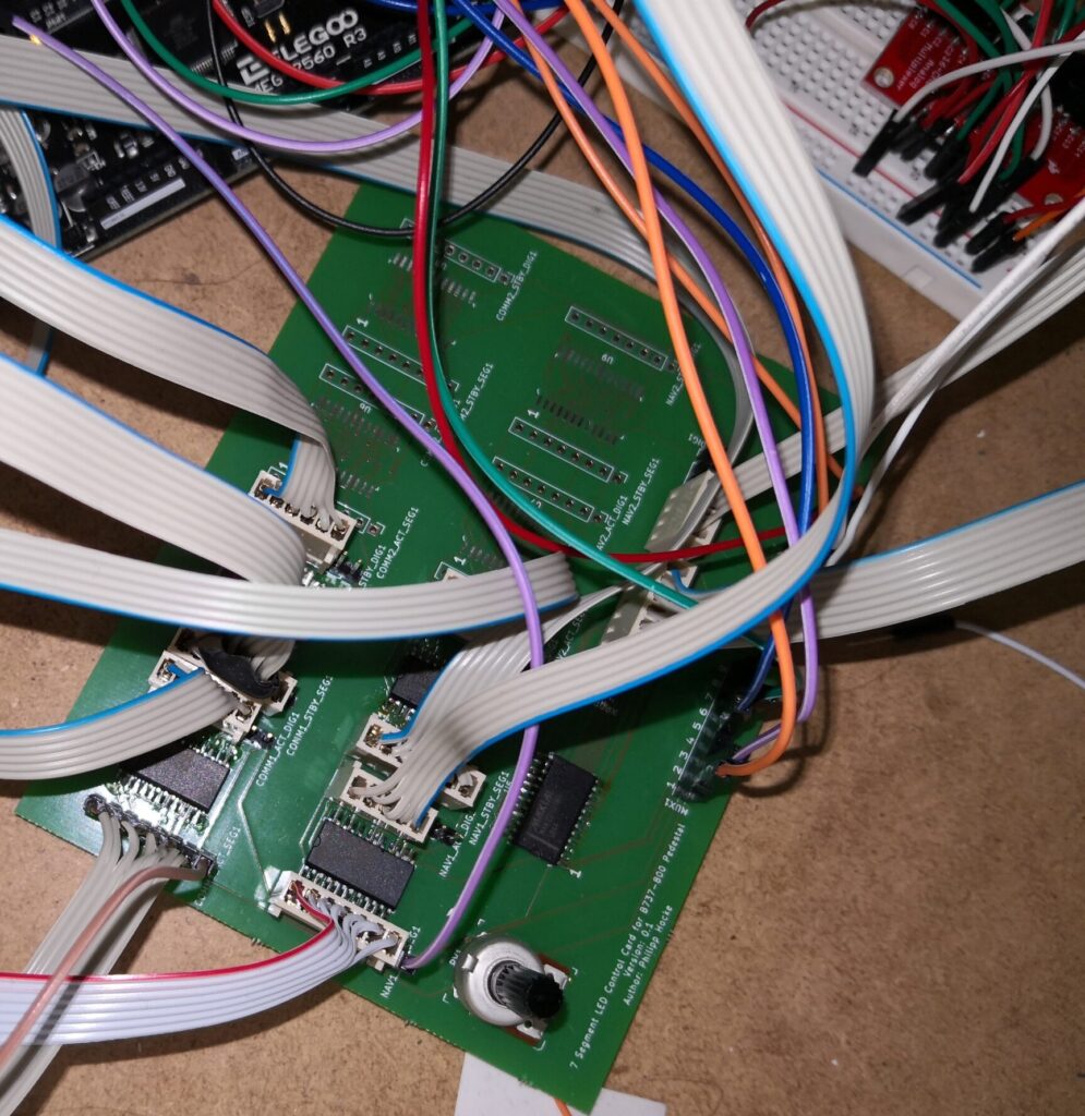
After soldering all required ICs + connectors I hooked up the instruments, to see if all of them worked as expected, and they did, safe one. NAV1_STBY did not show anything at all, not even one single digit.
I started checking if the digits were ok by connecting them to one of the other ICs. They were. Next thing was to check the cables. They were ok aswell.
So it was a problem with the PCB or maybe even the IC itself. So i got the card out the pedestal again and checked all connection between the pins and contacts on the IC. I turned out, that Pin1 (which is DIN) was not soldered correctly to the PCB. There was soldering on the foot – but only on the foot. No soldering tin between the connector and the PCB itself. It took me a while see that. I actually had to use a magnifying glass, it was almost impossible to see without it – at least for me.
After I corrected the problem, I hooked everything up again and finally all digits were up and running.
A problem that is still unsolved are the dot points. I the picture above you can see a single wire connected to COMM1_ACT segment nr. 8. The reason for that is, that I am using Opencockpit’s 7 Segment Display PCBs, which is a nice way of having an organized way of handling the connection to the digits. You just solder the digits to the board and you hook them up with 7 wires – for the segments – and n wires for the amount of digits you have on the PCB. The 8th segment – the dot point – is not wired. To get the dot point working – you have to directly wire the segment on the digit you want to use. When I used OC’s hardware, I wired both digits of ACT and STBY into one circuit and connected them to one pin of the outputs card. The MAX7219 IC can drive the dp seperately. For the moment ACT and STBY of both NAV and COMM are still in one circuit and are connected to the dp pin of the IC. This has the effect, that the dot point is brighter on the active side, than it is on the standby side. For the moment, this solution is ok, but I’ll need to rework that.
